


Research Article
Open Access
Design and Analysis of Collaborative
Automated Fiber Placement Machine
Xiaoming Zhang1, Wenfang Xie1*, Suong V. Hoa1, Rui Zeng2
1Department of Mechanical and Industrial Engineering, Concordia University, Canada
2State Key Laboratory of Virtual Reality Technology and Systems, Beijing University, Beijing, China
2State Key Laboratory of Virtual Reality Technology and Systems, Beijing University, Beijing, China
*Corresponding author: Wenfang Xie, Department of Mechanical and Industrial Engineering, Concordia University, 1455 De Maisonneuve Blvd.
West, Montreal, Quebec, Canada, H3G 1M8, Tel: +514-848-2424 x4193; Fax: +888-848-0321; E-mail:
@
Received: January 28, 2016; Accepted: February 16, 2016; Published: March 03, 2016
Citation: Zhang X, Xie W, Hoa SV, Zeng R (2016) Design and Analysis of Collaborative Automated Fiber Placement Machine. Int J Adv Robot Automn 1(1): 1-14. DOI: http://dx.doi.org/10.15226/2473-3032/1/1/00105
Abstract
The Automated Fiber Placement (AFP) machines have brought
significant improvement on composite manufacturing. However, the
current 7 DOF AFP machines normally consist of a 6 Degree-of-Freedom
(DOF) serial robot and 1 DOF rotatory mandrel are designed for the
manufacture of airframe components, which are usually shallow shells
or tubes. They are not capable of handling some applications with more
complex shapes. This paper presents the design and analysis of a 13
DOF collaborative AFP machine which consists of a 6 DOF manipulator,
a 6-RSS (Revolute Spherical Spherical ) parallel robot and a spindle
holding the mandrel (1 DOF) mounted on the platform of parallel robot.
The collaborative machine modeling is carried out and the motion of
the designed system is simulated in SimMechanics/ Matlab. The inverse
kinematic models for both parallel and serial manipulators are established
for path planning. In addition, the workspaces and singularities analysis
of the collaborative AFP machine are carried out. The case study on
three typical structures is presented and the simulation example for
manufacturing of a hemisphere structure is provided. The simulation
results show that the collaborative AFP machine could enlarge the
manufacturing workspace, simplify the trajectory planning and enhance
the production efficiency compared with the current 7 DOF AFP machine.
Keywords: Collaborative AFP, Parallel robot, Modeling, SimMechanics / Solidworks, Workspace, Kinematics
Keywords: Collaborative AFP, Parallel robot, Modeling, SimMechanics / Solidworks, Workspace, Kinematics
Introduction
Composite materials are being widely used in many
areas such as aerospace, automobiles, wind turbines,
civil infrastructures [1]. These materials are generally
lightweight and offer attractive strength-to-weight and
stiffness-to-weight ratios over the traditional structural
materials, such as steel, aluminum [2]. However, the
traditional methods of producing composite components
involve manual lay-up and tape-laying. These processes
are time-consuming, labor intensive and hazardous, with
high-material scrap rate and low repeatability [3,4].
The AFP machines have brought significant improvement on the manufacture of composite in terms of speed of material deposition, repeatability, good compaction, and reduction of waste [5]. But most AFP machines are designed for the manufacture of airframe components, which are usually shallow shells or tubes, and are not capable of handling some applications with more complex shapes. To be able to expand the manufacture capabilities of AFP machines in a simple and low cost way, it is necessary to increase the number of degrees of freedom of the robotic system.
One way is using another manipulator to hold the mandrel to be manufactured. The advantages of the integrated AFP manufacturing work cell using two serial manipulators are the large workspace and the dexterity to lay the fiber to manufacture the more complex geometry like human arms. But the load carrying capacity and the precision positioning capability are rather poor due to the cantilever structure of the serial manipulator [6]. For the applications of AFP machine where high load carrying capacity and precise positioning are of paramount importance, an alternative to such serial manipulators manufacturing work cell is desirable.
With the better stiffness and precise positioning capability [7], a 6 degree-of-freedom (DOF) parallel robot is introduced to AFP machines and a spindle is mounted on the platform to hold the mandrel [8]. The collaborative AFP manufacturing workcell is expected to be able to manufacture more intricate components and improve the product rate of the manufacturing compared with the current AFP machine. To our best knowledge, there is no application using the collaborative system (constructed with one parallel robot, one serial robot and one rotary stage) for AFP. And the most of the reported collaborative robotic systems usually consist of two serial robots used in other machining applications. The research on the design and analysis of the collaborative robotic system consisting of two different robots for AFP is very rare. In this paper, a 13 DOF collaborative AFP machine is designed by replacing the current 1 DOF mandrel holder with a 6-RSS (Revolutespherical- spherical) parallel robot and collaborating with a 6DOF serial robot. This paper aims at investigating the feasibility of applying such collaborative machine for fiber placement manufacturing. Hence the research topics include kinematic modeling, workspace analyzing and path planning of this 13 DOF machine.
For the serial manipulator, the forward and inverse kinematics is well-established. However, for the 6-RSS parallel manipulator, the forward kinematics poses a challenge due to the unique structure of fully parallel and closed-kinematic chains. Moreover, there might be multiple solutions to the forward kinematic equations [10- 12]. In this paper, the kinematic modeling of the designed system is carried out and the motion of the system is simulated in SimMecanics/Matlab. The inverse kinematic models of both serial and parallel manipulators are built for the path planning of fiber placement.
Finding the workspace free from singularities is very important for operating the collaborative AFP machine. One of the major disadvantages of parallel robot is the very limited and complicated workspace which is a highly coupled entity. Hence, for the parallel robots with more than three degree-of-freedoms, there will be no possible graphical illustration of the robot workspace. In the academic community, different types of subsets of the complete workspace are usually determined and the most popular one is the constant-orientation workspace which is the three–dimensional volume that can be attained by a point of the mobile platform while the platform is kept at a constant orientation [14-16]. Therefore, in order to get a good understanding of the parallel robot’s complete workspace, a series of constant-orientation workspaces for various orientations have to be studied. As the numerical methods, depending on the discretization step, give only an approximation of the shape of the workspace [17], the geometrical approaches are apparently faster, more intuitive, and accurate to analyze the workspace of parallel robots. The constant orientation workspace can be obtained by the intersection of six so-called vertex spaces and easily programmed in computer-aided design software such as Solid works [18-20]. In this paper, a geometrical method is used to analyze the workspace of the collaborative AFP machine and the singularity constraint condition is given for the parallel robot.
The path planning for the two 6DOF robots is a key technique for the fibre placement. In this paper, the manufacturing process is decomposed across the two robots involved [25]. The path planning decomposition follows the basic principle, i.e. to keep the fiber placement tip perpendicular to the surface mandrel without causing any collision and singularities while the motions of both robots are kept as simple as possible. To validate the developed modeling, workspace analysis and the path planning, a case study on three typical structures has been carried out and a simulation example for a bowl sample manufacturing is given to illustrate the mechanism of the designed collaborative AFP machine. The simulation results show that designed collaborative AFP machine could be able to enlarge the workspace to produce larger shape and simplify the path planning compared with the current AFP machine. Also, the designed machine can make the fiber placement process more flexible and can enhance the production efficiency.
The paper is organized as follows. In Section 2, the collaborative model is built and simulated in SimMechanics/Matlab and the inverse kinematic models are established for trajectory planning. The analysis of workspace and singularities of parallel platform is given in Section 3. In Section 4, path planning decomposition for collaborative AFP machine is introduced. In Section 5, three study cases are presented and a simulation example of hemisphere (bowl) manufacturing is provided. Finally, the simulation results validate the effectiveness of the proposed collaborative AFP manufacturing machine.
The AFP machines have brought significant improvement on the manufacture of composite in terms of speed of material deposition, repeatability, good compaction, and reduction of waste [5]. But most AFP machines are designed for the manufacture of airframe components, which are usually shallow shells or tubes, and are not capable of handling some applications with more complex shapes. To be able to expand the manufacture capabilities of AFP machines in a simple and low cost way, it is necessary to increase the number of degrees of freedom of the robotic system.
One way is using another manipulator to hold the mandrel to be manufactured. The advantages of the integrated AFP manufacturing work cell using two serial manipulators are the large workspace and the dexterity to lay the fiber to manufacture the more complex geometry like human arms. But the load carrying capacity and the precision positioning capability are rather poor due to the cantilever structure of the serial manipulator [6]. For the applications of AFP machine where high load carrying capacity and precise positioning are of paramount importance, an alternative to such serial manipulators manufacturing work cell is desirable.
With the better stiffness and precise positioning capability [7], a 6 degree-of-freedom (DOF) parallel robot is introduced to AFP machines and a spindle is mounted on the platform to hold the mandrel [8]. The collaborative AFP manufacturing workcell is expected to be able to manufacture more intricate components and improve the product rate of the manufacturing compared with the current AFP machine. To our best knowledge, there is no application using the collaborative system (constructed with one parallel robot, one serial robot and one rotary stage) for AFP. And the most of the reported collaborative robotic systems usually consist of two serial robots used in other machining applications. The research on the design and analysis of the collaborative robotic system consisting of two different robots for AFP is very rare. In this paper, a 13 DOF collaborative AFP machine is designed by replacing the current 1 DOF mandrel holder with a 6-RSS (Revolutespherical- spherical) parallel robot and collaborating with a 6DOF serial robot. This paper aims at investigating the feasibility of applying such collaborative machine for fiber placement manufacturing. Hence the research topics include kinematic modeling, workspace analyzing and path planning of this 13 DOF machine.
For the serial manipulator, the forward and inverse kinematics is well-established. However, for the 6-RSS parallel manipulator, the forward kinematics poses a challenge due to the unique structure of fully parallel and closed-kinematic chains. Moreover, there might be multiple solutions to the forward kinematic equations [10- 12]. In this paper, the kinematic modeling of the designed system is carried out and the motion of the system is simulated in SimMecanics/Matlab. The inverse kinematic models of both serial and parallel manipulators are built for the path planning of fiber placement.
Finding the workspace free from singularities is very important for operating the collaborative AFP machine. One of the major disadvantages of parallel robot is the very limited and complicated workspace which is a highly coupled entity. Hence, for the parallel robots with more than three degree-of-freedoms, there will be no possible graphical illustration of the robot workspace. In the academic community, different types of subsets of the complete workspace are usually determined and the most popular one is the constant-orientation workspace which is the three–dimensional volume that can be attained by a point of the mobile platform while the platform is kept at a constant orientation [14-16]. Therefore, in order to get a good understanding of the parallel robot’s complete workspace, a series of constant-orientation workspaces for various orientations have to be studied. As the numerical methods, depending on the discretization step, give only an approximation of the shape of the workspace [17], the geometrical approaches are apparently faster, more intuitive, and accurate to analyze the workspace of parallel robots. The constant orientation workspace can be obtained by the intersection of six so-called vertex spaces and easily programmed in computer-aided design software such as Solid works [18-20]. In this paper, a geometrical method is used to analyze the workspace of the collaborative AFP machine and the singularity constraint condition is given for the parallel robot.
The path planning for the two 6DOF robots is a key technique for the fibre placement. In this paper, the manufacturing process is decomposed across the two robots involved [25]. The path planning decomposition follows the basic principle, i.e. to keep the fiber placement tip perpendicular to the surface mandrel without causing any collision and singularities while the motions of both robots are kept as simple as possible. To validate the developed modeling, workspace analysis and the path planning, a case study on three typical structures has been carried out and a simulation example for a bowl sample manufacturing is given to illustrate the mechanism of the designed collaborative AFP machine. The simulation results show that designed collaborative AFP machine could be able to enlarge the workspace to produce larger shape and simplify the path planning compared with the current AFP machine. Also, the designed machine can make the fiber placement process more flexible and can enhance the production efficiency.
The paper is organized as follows. In Section 2, the collaborative model is built and simulated in SimMechanics/Matlab and the inverse kinematic models are established for trajectory planning. The analysis of workspace and singularities of parallel platform is given in Section 3. In Section 4, path planning decomposition for collaborative AFP machine is introduced. In Section 5, three study cases are presented and a simulation example of hemisphere (bowl) manufacturing is provided. Finally, the simulation results validate the effectiveness of the proposed collaborative AFP manufacturing machine.
System Modeling
Setup of the Collaborative AFP MachiningSystem
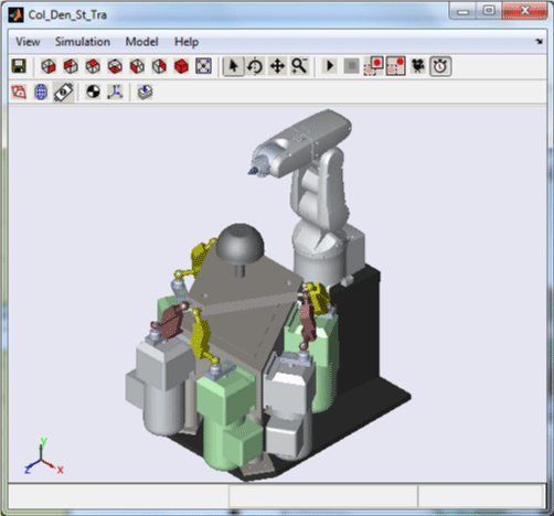
The experimental setup of the collaborative AFP
machine consists of one 6 DOF serial manipulator, one
6 degree-of-freedom parallel robot and a spindle is
mounted on the platform, as shown in Figure 1. The serial
manipulator is Denso 6-Axis robot, model VP6242G,
supplied with Quanser open-architecture control module
which has all capabilities of an industrial system and is
interfaced to QUARC. The fiber processing head will be
attached to the robot’s end-effector. The 6-RSS parallel
robot we used is Electric Motion System, model 710LP-
6-500-220, provided by Servo & Simulation Inc., which
contains six identical kinematic chains connecting the
base and the moving platform. Each connecting chain is
composed of one horizontal revolute joint mounted on the
base and two spherical joints. The motors and encoders

Figure 1: The collaborative AFP machine.
are located at the revolute joints on the base. The one
degree-of-freedom spindle consists of one rotary stage
and one three-jaw chuck. The rotary stage we used is
AGR75-NC-9DU-BMS-R-3 with soloist CP controller from
Aerotech Inc., which is mounted on the upper platform of
the parallel robot. The three-jaw chuck is attached to the
rotary stage to hold the mandrel. The pose of the mandrel
can be controlled by the parallel robot.
The working principle of the collaborative AFP machine mimics the process of two hands lay-up. The serial robot holding the fiber process head is served as one hand. Through this hand, the tows fed from the fiber processing head are laid onto the mandrel. The parallel manipulator holding the mandrel by the three-jaw chuck is served as the other hand. The rotary axis of three-jaw chuck is perpendicular to the upper platform of parallel robot. The pose of the mandrel can be adjusted by the parallel robot. During the fiber placement process, the end-effector of serial robot must be orientated in such a way that the pressure of fiber processing head’s compaction roller always be normal to the surface of mandrel.
The working principle of the collaborative AFP machine mimics the process of two hands lay-up. The serial robot holding the fiber process head is served as one hand. Through this hand, the tows fed from the fiber processing head are laid onto the mandrel. The parallel manipulator holding the mandrel by the three-jaw chuck is served as the other hand. The rotary axis of three-jaw chuck is perpendicular to the upper platform of parallel robot. The pose of the mandrel can be adjusted by the parallel robot. During the fiber placement process, the end-effector of serial robot must be orientated in such a way that the pressure of fiber processing head’s compaction roller always be normal to the surface of mandrel.
SimMechanics Model of the Collaborative AFP Machine
The main objective of this paper is to investigate the
feasibility of applying the designed collaborative AFP
machine to structure manufacturing. To achieve this
objective, we use Matlab/SimMechanics to build the
kinematic model for validating the subsequent workspace
analysis and path planning. SimMechanics software is a
block diagram modeling environment for the engineering
design and simulation of rigid body machines and their
motions, which interfaces seamlessly with Simulink and
MATLAB. The visualization tools of SimMechanics software display and animate simplified standard geometries of 3
dimension machines, before and during simulation. Figure
2 shows the SimMechanics model of the collaborative AFP
machine. The top part is the SimMechanics model of Stewart
platform. The six identical kinematic chains connect the
base and the moving platform. In each connecting chain, the
proximal link is connected to the base by a revolute joint.
The ends of the distal link are connected the proximal link
and the moving platform by two spherical joints. Six drive
signals are input to the actuator port of the six revolute
joints. In addition, a spindle is mounted on the platform,
connected by a revolute joint, to hold the mandrel. The
bottom part of the figure shows the SimMechanics model
of Denso Robot. Six revolute joints containing drive signals
connect seven components including the end effector. The
bases of the Stewart platform model and Denso Robot
model are welded together. The positions and orientations
of the two end effectors of the Stewart platform and the
manipulator are measured by the sensors and output for
further simulation.
The Inverse Kinematics Analysisof Collaborative AFP
Machine
Inverse Kinematic of Serial Robot: The serial
robot model is built based on Denso Robot. The (D-H)
Denavit–Hartenberg parameters, which represent the
four parameters associated with a particular convention
for attaching reference frames to the links of robot
manipulator, are shown in Table 1.
There are multiple solutions to the inverse kinematics of a serial-link manipulator. The shortest distance rule is used to choose a solution closest to the current manipulator [9], shown in Equation (1).
There are multiple solutions to the inverse kinematics of a serial-link manipulator. The shortest distance rule is used to choose a solution closest to the current manipulator [9], shown in Equation (1).

Figure 2: Simulation Modelof the Parallel Robot.
Table 1: Link Parameters.

where θi
is the rotational angle of the i joint, θni is the
n solution.
Inverse Kinematic of Parallel Robot
The inverse kinematics of parallel robot is commonly
used for trajectory generation. As described above, the
inverse kinematics of the 6-RSS parallel robot is the
mapping from the position and orientation of the end
effect to the actuator angles, referring to the mechanism
shown in Figure 3.
The end of each proximal link in the identical kinematic chain is connected to one of the six vertices of the base, point Ai . The coordinates of these points Ai (XAi YAi ZAi) in terms of the base frameOare fixed and the values are shown in Equation 2.
The end of each proximal link in the identical kinematic chain is connected to one of the six vertices of the base, point Ai . The coordinates of these points Ai (XAi YAi ZAi) in terms of the base frameOare fixed and the values are shown in Equation 2.
where b and d are the side lengths of the base semiregular
hexagon. The vectors along line OAi are denoted
as ai.
The lengths of all proximal links are equal and denoted by r and the vector is defined as The connected points of the distal links and the proximal links are referred to as Bi . The horizontal rotational angles θi are controlled by the motors at revolute joints. The vectors along line OBi in terms of the base frameO are denoted by bi , shown in Equation 3.
The lengths of all proximal links are equal and denoted by r and the vector is defined as The connected points of the distal links and the proximal links are referred to as Bi . The horizontal rotational angles θi are controlled by the motors at revolute joints. The vectors along line OBi in terms of the base frameO are denoted by bi , shown in Equation 3.
Then the top ends of the distal links in the connecting
chains are connected to the six vertices of the mobile
platform, which are denoted as point Ti . The coordinates
of these points Ti ( XTi,YTi ,ZTi ) with respect to the upper
frameO' are fixed, shown in Equation (4).
Where a and c are the side lengths of the top semiregular
hexagon. The vectors along line O'Ti are denoted
as ti with respect to the upper platform. These coordinates
vary in terms of the base frame when the platform moves.
The position of the upper platform with respect to the
base frame is defined by vector c , along the line OO' . The
vectors along lines OTi are denoted by di = c + Rti, which
are the coordinates of all vertices of the upper platform
with reference to the base frame (XTi YTi ZTi) . The transformation matrix R , defined by three Euler angles,
describes the orientation of the upper platform.
The unit vector along distal links L are denoted by ni
, which is
By taking the square of both sides of Equation (5), one has
And
From the vector r and the vertices coordinates of
points Ai and Ti with reference to the base frame, Eq. (7)
reduces to
And
where
and The inequality holds.And is the solution to the inverse kinematics
Workspaces and Singularities Analysis of
Collaborative AFP machine
Geometrical Approach for the Workspace Analysis of
Parallel Robot
In this paper, the three–dimensional workspace can be
attained by keeping a center point o' (x, y, z) of the
mobile platform at a constant orientation. In order to get the position points of o', the transformation matrix defined as , and the position of points in terms of the base frame O is obtained as




where [x y z]' is the position of center point
o' in terms of the base frameO,R is the orientation
matrix between the mobile platform and the base
frame mentioned above, which is constant in this case,
[ M(1,1) M(2,1) M(3,1)]T is determined by rotation matrix R , which is also constant in this case.
So, Eq. (6) could be rewritten as
So, Eq. (6) could be rewritten as
In fact, the solution of Equation 13 is six clusters of
spherical, where the radius is L , the spherical center is
Oi(xi,yi,zi ) , which varies with the change of actuator
angles θi
.
Take 1 O for example, from Equation 13 and 12,
Take 1 O for example, from Equation 13 and 12,
From Equation 14 and Equation 16, one has
Thus, one has
Where
And xo1 ,zo1 and y1 are only dependent upon the
orientation matrix of the mobile platform R , Equation
18 represents a circle with the center point Ooi(xoi zoi)
, the radius r in xz plane and the height y1 in the 3D
Cartesian space. Therefore, for a given orientation R
, Equation 13 represents six clusters of spherical whose
center points Oi(xi, yi, zi)locate on the circles with the
center points Ooi(xoi zoi), the radius r and the height y1 .
When r ≥ L , one cluster of spheres defined by Equation 13 is a torus shown in Figure 4. In the case where we have r < L , and r = 40mm, L =160mm , one cluster of spheres could be represented as a vertex space shown in Figure 5A. For a given orientation of the mobile platform with Euler anglesφ =θ =ψ = 0o , the workspace of the parallel robot can be obtained as the intersection of the six vertex spaces shown in Figure 5B.
Using the SimMechanics model, the limitation of Euler angles of the mobile platform φmin ,φmax ,θmin ,θmax ,ψmin,ψmax can be tested. Six sets of constant-orientation workspaces with six limitations Euler angles could be defined using the above method. The test results for the 6-RSS parallel platform are shown in Table 2.
The maximum workspace could be found as the intersection of all constant-orientation workspaces for any angle between[φmin φmax] ,[θmin θmax] and [ψmin ψmax].
When r ≥ L , one cluster of spheres defined by Equation 13 is a torus shown in Figure 4. In the case where we have r < L , and r = 40mm, L =160mm , one cluster of spheres could be represented as a vertex space shown in Figure 5A. For a given orientation of the mobile platform with Euler anglesφ =θ =ψ = 0o , the workspace of the parallel robot can be obtained as the intersection of the six vertex spaces shown in Figure 5B.
Using the SimMechanics model, the limitation of Euler angles of the mobile platform φmin ,φmax ,θmin ,θmax ,ψmin,ψmax can be tested. Six sets of constant-orientation workspaces with six limitations Euler angles could be defined using the above method. The test results for the 6-RSS parallel platform are shown in Table 2.
The maximum workspace could be found as the intersection of all constant-orientation workspaces for any angle between[φmin φmax] ,[θmin θmax] and [ψmin ψmax].
Figure 3: The Parallel Robot Mechanism.
Figure 4: The Section View of Cluster of Spheres.
Figure 5: Workspace of Parallel Robot with Given Orientation.
Table 2: The Limitation of Euler Angles.
Singularities Analysis of Parallel Robot
The parallel robot will lose its designated motion and
working capability if the singularities are not excluded
from its working area. Thus, the singularities analysis is
one of the main concerns of system design using parallel
robots [21].
Differentiating Equation (6) with respect to time
Differentiating Equation (6) with respect to time
and substituting Equation 5, to Equation 21, one can
obtain
The above equation can be simplified and written in
matrix form using Equation (9) and Equation (10)
where ω is the angular velocity of the upper platform. is the vector of active joint rates. is ti expressed in base frame. Eq.(24) can be written as
where two matrices A and B are referred to as Jacobian
matrices. The first, second and third kinds of singularities
occur when matrix B is singular, matrix A is singular and
matrices A and B are simultaneously singular respectively
[22].
For the first kind of singularity, the determinant of matrix det(B) = 0 which means one (or some) of Ti Bi is perpendicular to the instantaneous velocity of Bi , or Ti Bi happens to projecting onto the Ai Bi in xoz plane. The sufficient and necessary condition for det(B) = 0 is "the ball with a center Ti tangents to the circle with a center Ai in the single point Bi ". Figure 6 shows three kinds of tangent, where Figure 6 (a-b) shows the situation that the only one inverse kinematic solution exists in ith chain. The numbers of inverse kinematic solution as shown in Figure 6 (a-b) or the coordinate of Ai as shown in Figure 6 can be used directly as a constraint for the first kind of singularity.
Based on line geometry [23], the second kind of singularity occurs when the orientation vector of the forces and torques acted on the end-effector are coupling to each other. In other word, real singularity for 6-RSS parallel robot occurs when det(A) = 0 . Normally, the sign of det(A) is an effect judgment constraint for the first kind of singularity in the engineering application. Unfortunately, the existence of degenerate singularity may overthrow this constraint. To avoid the perturbation
For the first kind of singularity, the determinant of matrix det(B) = 0 which means one (or some) of Ti Bi is perpendicular to the instantaneous velocity of Bi , or Ti Bi happens to projecting onto the Ai Bi in xoz plane. The sufficient and necessary condition for det(B) = 0 is "the ball with a center Ti tangents to the circle with a center Ai in the single point Bi ". Figure 6 shows three kinds of tangent, where Figure 6 (a-b) shows the situation that the only one inverse kinematic solution exists in ith chain. The numbers of inverse kinematic solution as shown in Figure 6 (a-b) or the coordinate of Ai as shown in Figure 6 can be used directly as a constraint for the first kind of singularity.
Based on line geometry [23], the second kind of singularity occurs when the orientation vector of the forces and torques acted on the end-effector are coupling to each other. In other word, real singularity for 6-RSS parallel robot occurs when det(A) = 0 . Normally, the sign of det(A) is an effect judgment constraint for the first kind of singularity in the engineering application. Unfortunately, the existence of degenerate singularity may overthrow this constraint. To avoid the perturbation
Figure 6: Geometric Relationship of Singularities
from degenerate singularity surface, the Cauchy Index of
A can be add to determine the singularity based on the
conclusion of [24]. Then for any two very closing points
p1,p2 ∈N , the singularity constraint condition is given
as follows
as follows
1. , line in a simple connected domain;
2., line cross a non-degenerate singularity surface;
3. , and in line , min , line cross a degenerate singularity surface.
Where is Cauchy index of in the point i N is the workspace of 6-RSS parallel robot.
Where is Cauchy index of in the point p1 , N is the workspace of 6-RSS parallel robot.
2., line cross a non-degenerate singularity surface;
3. , and in line , min , line cross a degenerate singularity surface.
Where is Cauchy index of in the point i N is the workspace of 6-RSS parallel robot.
Where is Cauchy index of in the point p1 , N is the workspace of 6-RSS parallel robot.
Workspace of Collaborative AFP Machine
As the workspace for the serial robot has been well
studied in the literature, we can find the workspace of
collaborative AFP machine as shown in Figure 7.
The workspace of the parallel robot is the constantorientation workspace with the Euler angles . The workspace of the Denso robot is defined as the intersect point of the last three joint axes.
The workspace of the Denso robot is defined as the intersect point of the last three joint axes.
The workspace of the parallel robot is the constantorientation workspace with the Euler angles . The workspace of the Denso robot is defined as the intersect point of the last three joint axes.
The workspace of the Denso robot is defined as the intersect point of the last three joint axes.
Path Planning Decomposition for Collaborative
AFP Machine
Multi-robots system can meet the flexibility and
adaptability needs during manufacturing processes. It can be defined by decomposing the overall process across
tasks, across robots or hybrid. Our collaborative AFP
machine is robot-based decomposition whose individual
self-contained entities are the robots involved in the whole
process [25].
Path Planning Composition Algorithm
Path planning decomposition defines the trajectory
of each robot independently to avoid collision with each
other. However, due to our application, the pressure of
fiber processing head’s compaction roller must be normal
to the surface of mandrel and the axis of the compaction
roller should always keep perpendicular to the trajectory
path during the manufacturing processes. The mandrel is
mounted on the rotary stage which is fixed on the upper
platform of parallel robot. It indicates that the relative
attitudes between the end-effectors of two robots are fixed.
As shown in Figure 8, when there is translation movement from the original point of parallel robot’s end-effectort o _P',the original point of serial robot’s end-effector
Figure 7: The Cross-Sectional View of the Workspace of Collaborative
AFP Machine.
Figure 8: The Relative Movement between the Two End-effectors.
O_ D needs to move to O _ D' with the same distance. When
there is orientation movement from the original point of
parallel robot’s end-effector O_ P' to O _ P" , the original
point of serial robot’s end-effector O_ D' needs to move
to O _ D" in the reference of original point _ ' with the
same angle, which keeps the relative pose between the
two end-effectors the same. Subjected to such constrain,
the collaborative robot will be free of collision between the
two robots during manufacturing processes. If the desired
path is determined, the relative pose between the two
end-effectors cannot be changed. When one of the endeffector
reaches its pose limitation, the other end-effector
can offset the gap between such limitation and the desired
pose, which improves the manufacturing ability of the AFP
machine.
The basic principle of decomposing the multi-robot system is to keep the fiber placement tip perpendicular to the surface mandrel without causing any collision and singularities while the motions of both robots are kept as simple as possible. Based on the analyses above, the desired path planning can be decomposed to the trajectory of serial robot, rotary movement of rotary stage and the adjust movement of parallel robot. For example, the spiral curve can be decomposed to rotary movement for rotary stage and line for serial robot. The orientation of the serial robot’s end-effector α should always be the same as the desired path shown in Figure 9. The plane curve can be decomposed to translation the movement for the end effector of parallel robot with orientation β and the line for serial robot with orientationω , whereβ ,ω can be either constant or variable angle based on the manufacturing case and satisfy the equation α = β +ω , as shown in Figure 10.
For general situation, in order to simplifying the decomposition process, we normally let the parallel robot hold still. We only control the parallel robot to offset the gap between the desired path and the actual path to improve the accuracy and to compensate the pose limitation of serial robot when it encounter unreachable points.
The basic principle of decomposing the multi-robot system is to keep the fiber placement tip perpendicular to the surface mandrel without causing any collision and singularities while the motions of both robots are kept as simple as possible. Based on the analyses above, the desired path planning can be decomposed to the trajectory of serial robot, rotary movement of rotary stage and the adjust movement of parallel robot. For example, the spiral curve can be decomposed to rotary movement for rotary stage and line for serial robot. The orientation of the serial robot’s end-effector α should always be the same as the desired path shown in Figure 9. The plane curve can be decomposed to translation the movement for the end effector of parallel robot with orientation β and the line for serial robot with orientationω , whereβ ,ω can be either constant or variable angle based on the manufacturing case and satisfy the equation α = β +ω , as shown in Figure 10.
For general situation, in order to simplifying the decomposition process, we normally let the parallel robot hold still. We only control the parallel robot to offset the gap between the desired path and the actual path to improve the accuracy and to compensate the pose limitation of serial robot when it encounter unreachable points.
Path Planning Model of Collaborative AFP Machine
Figure 11 shows the simulation model of path planning
in SimMechanics. At the left side of the diagram block, with
the parameter inputs, the block “Trajectory Generator”
generates the desired positions and orientations of the
working frames for both parallel robot and Denso robot as
well as the desired rotation of mandrel. Then, the desired
positions and orientations are transferred to matrix. With
the inputs of the matrices, the relative values for each leg
and the rotation are calculated by the inverse kinematics
blocks. And the movements in the SimMechanics are
Figure 9: The Decomposition of Spiral Curve.
Figure 10: The Decomposition of Plane Curve.
Figure 11: Simulation Model of Path Planning.
actuated based on such values. In the SimMechanics
model, the positions and orientations of the tool frame for
the two robots are measured by the sensors and the values
of the motors’ encoders are outputted as the feedback for
the controller. The running simulation in SimMechanics is
shown as Figure 12.
Case Study
To illustrate the mechanism of the designed
collaborative fibre placement machine, we present the
examples for the bowl manufacturing, which consists of

Figure 12: Simulation in SimMechanics.
plane surface and curved surface, and Y shape structure
manufacturing.
Case One: Plane Surface
In order to generate the paths for fibre layup, the initial
path must be formulated first. The next path is found by
perpendicularly offsetting the initial path along the surface
by the required offset distance, the total width of tows for
multiple tows layup. The offset path should be extended to
the boundary when it does not reach the surface boundary
or the offset path falls outside the range of the mold [2].
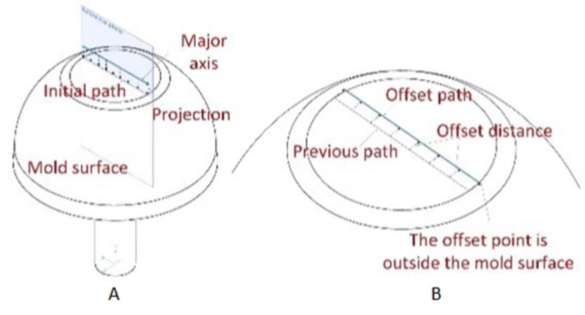
For a given free-form shaped structure, the initial path is formulated by the surface-plane intersection strategy.
The major axis is specified to pass through the point , and then a projection of the major axis forms the reference plane
Where , and
For a given free-form shaped structure, the initial path is formulated by the surface-plane intersection strategy.
The major axis is specified to pass through the point , and then a projection of the major axis forms the reference plane
Where , and
The surface-plane intersection equation can be formed by substituting the parametric equation of the mold surface
which is defined by the set of parameters u and v .
By solving Equation 27, the coordinates of the
intersection points (u,v) are obtained. In this case of
producing the plane surface of the bowl, the initial path is
a straight line on the x-z plane, shown in Figure 13A.
To achieve a uniform AFP path over a mold, the neighbouring paths must be offset along the surface a distance of the total width of tows in a perpendicular direction from the given path. For the free-form shaped structure, the offset direction at one point is actually a curve, which is along the mold and perpendicular to the reference path at that point. This curve is formulated by surface-plane intersection strategy as well. However, for the plane surface case, the offset direction is along x direction on x-z plane, as shown in Figure 13B.
Normally, there are two reasons for the incomplete offset. The first is that the offset points fall outside the range of the mold. The other reason is that the original points are not on the mold. The offset path should be extended to the boundary by calculating the extrapolated points and adding them to the existing points when it does not reach the surface boundary, illustrated in Figure 13B.
As mentioned above, the roller mounted on the end effector of the serial robot must be always normal to the mold surface. Calculating the position and orientation of the roller at any moment in the AFP process are necessary. The decomposing process of this case is that: the parallel robot holds still; the trajectory for the end effector of the serial robot is parallel lines and the orientation of the roller
To achieve a uniform AFP path over a mold, the neighbouring paths must be offset along the surface a distance of the total width of tows in a perpendicular direction from the given path. For the free-form shaped structure, the offset direction at one point is actually a curve, which is along the mold and perpendicular to the reference path at that point. This curve is formulated by surface-plane intersection strategy as well. However, for the plane surface case, the offset direction is along x direction on x-z plane, as shown in Figure 13B.
Normally, there are two reasons for the incomplete offset. The first is that the offset points fall outside the range of the mold. The other reason is that the original points are not on the mold. The offset path should be extended to the boundary by calculating the extrapolated points and adding them to the existing points when it does not reach the surface boundary, illustrated in Figure 13B.
As mentioned above, the roller mounted on the end effector of the serial robot must be always normal to the mold surface. Calculating the position and orientation of the roller at any moment in the AFP process are necessary. The decomposing process of this case is that: the parallel robot holds still; the trajectory for the end effector of the serial robot is parallel lines and the orientation of the roller
Figure 13: The Path Planning for the Plane Surface.
on the serial robot is along y direction; rotary stage rotates
the mold with required angle to change the orientation of
tow for different layers.
Case Two: Curved Surface
For the curved surface of the bowl, the planning path
for the end effector of the serial robot is formulated by the
surface-plane intersection strategy, shown in Figure 14.
The Frenet-Frame at the offset point could be defined as
The Frenet-Frame at the offset point could be defined as
where e1 is the unit vector tangent to the curve; e2 is the
normal unit vector which guarantees the roller would
always be normal to the mold surface; e3is the bi-normal
unit vector which is the offset direction in this case.
The decomposing process of this case is that: the roller moves to one point with the orientation shown in Figure 14 and maintains still while the rotary stage rotates one circle. Then, the roller offsets to the next point along vector e3 with the total width tow-width and repeats the operation until the producing process completes.
The decomposing process of this case is that: the roller moves to one point with the orientation shown in Figure 14 and maintains still while the rotary stage rotates one circle. Then, the roller offsets to the next point along vector e3 with the total width tow-width and repeats the operation until the producing process completes.
Case Three: Y-Shape
As to the Y-shape surface, Figure 15 shows the
decomposing process of wrapping two branches without
cutting, which can be decomposed to trajectory of serial
robot and rotary movement of rotary stage. e2 is the
normal unit vector which guarantees the roller would
always benormal to the mold surface. After finishing
wrapping from branch A to branch B , another layer is
wrapped from branch B to branch C . Then, a new layer
is started from branch C to branch A and the wrapping
cycle is kept like this.
Simulation in SimMechanics for Bowl Manufacturing
To illustrate the designed collaborative AFP machine
for manufacturing composite structure with difference
complex shapes, the simulation of the collaborative AFP
on manufacturing a bowl structure is conducted and the
feasibility and the advantages of the proposed collaborative
system is validated.
The path planning equations are input into the
The path planning equations are input into the
Figure 14: The Trajectory Planning for the Curved Surface.
Figure 15: The Decomposition for Y-ShapeTrajectory.
"trajectory generator" block in SimMechanics to
decompose the desired trajectory into control signals for
serial robot, parallel robot and rotary stage separately, as
shown in Figure 11. The positions and orientations of the
end effectors of the serial robot and the parallel robot are
acquired by the sensors in the SimMechanics mold. The
path planning of AFP machine is illustrated in Figure 13
and Figure 14 bowl manufacturing.
Figure 16A shows the path planning of AFP machine when the parallel robot remains still where P_O represents the initial point of the serial robot’s tool coordinate system, C_D is the planning path of the serial robot, O_P is the tool frame of the parallel robot, O_D is the tool frame of the serial robot, the direction Z_D always be maintained normal to the mold surface, R represents the radius of the bowl, t_1 , t_2 indicate the two producing processes for plane surface and curved surface. Due to the limitation of the AFP machine’s workspace, the largest radius of the bowl the AFP machine could manufacture is R = 62 mm in SimMechanics. By adding the compensation of the parallel robot, the biggest radius is enlarged to R = 75 mm, as shown in Figure 16B. The tool frame O'_P of the parallel robot is obtained by rotating the initial frame O_ P about X axis by 4 ° and translating it 13 mm in y direction, 8 mm in z direction. The simulation process in SimMechanics is shown in Figure 17.
Figure 16A shows the path planning of AFP machine when the parallel robot remains still where P_O represents the initial point of the serial robot’s tool coordinate system, C_D is the planning path of the serial robot, O_P is the tool frame of the parallel robot, O_D is the tool frame of the serial robot, the direction Z_D always be maintained normal to the mold surface, R represents the radius of the bowl, t_1 , t_2 indicate the two producing processes for plane surface and curved surface. Due to the limitation of the AFP machine’s workspace, the largest radius of the bowl the AFP machine could manufacture is R = 62 mm in SimMechanics. By adding the compensation of the parallel robot, the biggest radius is enlarged to R = 75 mm, as shown in Figure 16B. The tool frame O'_P of the parallel robot is obtained by rotating the initial frame O_ P about X axis by 4 ° and translating it 13 mm in y direction, 8 mm in z direction. The simulation process in SimMechanics is shown in Figure 17.
Results Analysis
The simulation results indicate that the collaborative
AFP machine could be able to enlarge the workspace to
produce larger shape. Furthermore, with more degree-offreedom,
the AFP machine could simplify the path planning.
In the simulation for producing the curved surface, only a
simple two dimension curve is needed for the planning
path of the serial robot instead of more complicated space
curve for the current AFP. For a more complicated curved
surface such as the blade of engine, the planning path
Figure 16: The Planning Path for the Bowl Producing.
Figure 17: The Simulation Process in SimMechanics.
could be decomposed into two simpler curves operated
by the parallel robot and serial robot respectively in the
collaborative AFP machine. In addition, the proposed AFP
machine could manufacture both the plane surface and
the curved surface without changing any equipment in the
simulation process, which makes the producing process
more flexible and enhances the production efficiency and
process adaptability.
The position repeatability of Denso Robot is ±0.02 mm . The accuracy of parallel robot determined from the actuator encoder accuracy is ±1 mm . The accuracy of the collaborative AFP machine also depends on that of fiber processing head. Assuming the accuracy of fiber processing head is higher than ±1 mm ; the accuracy of the collaborative AFP is expected to be around ±1 mm
The position repeatability of Denso Robot is ±0.02 mm . The accuracy of parallel robot determined from the actuator encoder accuracy is ±1 mm . The accuracy of the collaborative AFP machine also depends on that of fiber processing head. Assuming the accuracy of fiber processing head is higher than ±1 mm ; the accuracy of the collaborative AFP is expected to be around ±1 mm
Conclusion
In this paper, a collaborative AFP machine is proposed
which consists of a 6-RSS parallel platform, a 6-degree-offreedommanipulator
and a spindle. The inverse kinematic
models for the serial robot and the parallel platform are
established for path planning. The workspaces of both
parallel robot and the collaborative AFP machine are
analyzed using geometrical method. The path planning
decomposition for the collaborative AFP machine is
proposed and the path planning model is implemented
in the SimMechanics. A case study on the structures with
three typical shapes has been conducted and a simulation
example for the manufacturing of a bowl is provided.
The SimMechanics simulation results show that, with
more degree-of-freedom, the proposed collaborative
AFP machine could enlarge the manufacture workspace,
simplify the trajectory planning and enhance the
production efficiency.
Further work will include applying the design and analysis results to an industrial collaborative AFP machine with fibre placement head.
Further work will include applying the design and analysis results to an industrial collaborative AFP machine with fibre placement head.
ReferencesTop
- Groppe D. Robots Improve the Quality and Cost-effectiveness of Composite Structures. Industrial Robot: An International Journal 2000;27(2):96-102.
- Ahrens M, Mallick V, Parfrey K. Robotic Based Thermoplastic Fibre Placement Process. Industrial Robot: An International Journal. 1998;25(5): 1148-1153.
- Bijan S, Gary C, Denny O, Alici G, Marcelo H, Ang JR. Trajectory generation for open-contoured structures in robotic fibre placement. Robotics and Computer-Integrated Manufacturing. 2007;23(4):380-394.
- Bijan S, Chee WF, Boon HT. Robotic fibre placement process planning and control. Assembly Automation. 2000;20(4):313-320.
- Bijan S, Gursel A, Chee WF, Gary C. Fabrication process of open surfaces by robotic fibre placement. Robotics and Computer-Integrated Manufacturing. 2004;20(1):17-28.
- Dasgupta B, Muthyunjaya TS. The Stewart platform manipulator: a review. Mechanism and Machine Theory. 2000;35(1):15-40.
- Zanganeh EK, Sinatra R, Angeles J. Kinematics and dynamics of a six-degree-of-freedom parallel manipulator with revolute legs. Robotica. 1997;15(4):385-394.
- Zhang XM, Xie WF, Hoa SV. Modeling and Workspace Analysis of Collaborative Advanced Fiber Placement Machine. ASME. International Mechanical Engineering Congress & Exposition. 2014; doi:10.1115/IMECE2014-38553.
- Wang QJ, Du JJ. A new solution for inverse kinematics problems of MOTOMAN robot. Journal of Harbin Institute of Technology. 2010;42(3):451-454.
- Nanua P. Waldron KJ, Murthy V. Direct Kinematic Solution of a Stewart Platform. IEEE Xplore. 1989;6(4):438-444.
- Merlet JP. Solving the Forward Kinematics of a Gough-Type Parallel Manipulator with Interval Analysis. SAGE. 2004;23(3):221-235.
- Baron L, Angeles J. The Direct Kinematics of Parallel Manipulators under Joint-Sensor Redundancy. IEEEXplore. 2000;16(1):12-19.
- Liu K, Fitzgerald JM, Lewis FL. Kinematic Analysis of a Stewart Platform Manipulator. IEEEXplore . 1993;40(2):282-293.
- Merlet JP. Determination of the Orientation Workspace of Parallel Manipulators. Springer. 1995;13(2):143-160.
- Bonev IA, Ryu J. A new Approach to Orientation Workspace Analysis of 6-DOF Parallel Manipulators. Mechanism and Machine Theory. 2001;36(1):15-28
- Monsarrat B, Gosselin CM. Workspace Analysis and Optimal Design of a 3-Leg 6-DOF parallel platform Mechanism. IEEEXplore. 2003;19(6):954-966.
- Ceccarelli M, Ottaviano E. A Workspace Evaluation of an Eclipse Robot. Robotica. 2002;20:299-313.
- Jiang QM, Gosselin CM. The Maximal Singularity-Free Workspace of the Gough-Stewart Platform for a Given Orientation. Research Gate. 2008;130(11):1123041-1123048.
- BonevIA, Gosselin CM. Geometrical algorithms for the computation of the constant-orientation workspace and singularity surfaces of a special 6-RUS parallel manipulator. Research Gate. 2002. doi: 10.1115/DETC2002/MECH-34257.
- Blaise J, Bonev I, Monsarrat B, Briot S, Lambert JM, Perron C. Kinematic characterisation of hexapods for industry. Industrial Robot: An International Journal 2010;37(1):79-88.
- Yang GL, Chen IM, Lin W, Angeles J. Singularity Analysis of Three-Legged Parallel Robots Based on Passive-Joint Velocities. Industrial Robot: An International Journal. 2001;17(4):413-422.
- Gosselin C, Angeles J. Singularity Analysis of Closed-Loop Kinematic Chains. Robotics and Automation, IEEE. 1990;6(3):281-290.
- Merlet JP. Singular configurations of parallel manipulators and grassmann geometry. Springer. 2005;391:194-212.
- Zeng R, Zhao YJ, Dai SL. The proper motion domain for the actuators of Stewart-Gough platform. IEEE Xplore. 2014. 1706-1711.
- Tzafestas ES. Agentifying the process: task-based or robot-based decomposition? IEE Xplore. 1994;1: 582-587.

